HP LaserJet M506, MFP M527, HP LaserJet Managed E50045, E52545 - Removal and replacement: Dual in-line memory module (DIMM)
HP LaserJet M506, MFP M527, HP LaserJet Managed E50045, E52545 - Removal and replacement: Dual in-line memory module (DIMM)
Introduction
This document provides the procedures to remove and replace the dual
in-line memory module (DIMM).
Before performing service
Turn the printer power off
-
Disconnect the power cable.
WARNING:
To avoid damage to the printer, turn the printer off, wait 30 seconds, and then remove the power cable before attempting to service the printer.
CAUTION:This part contains components that are electrostatic discharge (ESD) sensitive. To reduce the possibility of ESD damage, always touch the sheet-metal chassis to ground yourself before touching an ESD sensitive part.
Use the table below to identify the correct part number for your
printer. To order the part, go to www.hp.com/buy/parts.
|
Dual in-line memory module (DIMM) kit part number
|
|
|
E5K48-67902
G6W84-67902
|
Dual in-line memory module (DIMM) with instruction guide
(M527)
Slim dual in-line memory module (DIMM) with instruction
guide (M506)
|
Required tools
No special tools are required to install this part.
After performing service
Turn the printer power on
-
Connect the power cable.
-
Use the power switch to turn the power on.
Post service test
Make sure that the printer initializes to a Ready state.
Print a configuration page to make sure that the printer is
functioning correctly.
Step 1: Remove the formatter cover
-
Slide the cover toward the rear of the printer to remove it.Figure : Remove the formatter cover

Step 2: Remove the hard-disk drive (HDD)
NOTE:HDD models only. For all other models, skip this step and go to Step 3: Remove the dual in-line memory module (DIMM).
CAUTION:ESD-sensitive part.
-
Release the locking connector (callout 1), and then pinch the retainer (callout 2) to release it.Figure : Release the HDD
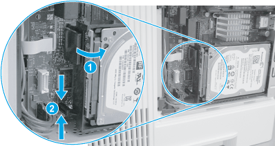
-
Rotate the connector end of the HDD out and away from the formatter (callout 1), and then slide it as shown (callout 2) to remove it.Figure : Remove the HDD

Step 3: Remove the dual in-line memory module (DIMM)
CAUTION:
NOTE:The M506 printers use a Slim dual in-line memory module (DIMM).
-
M506 only: Locate the DIMM component on the formatter, and then pull it straight off of the formatter to remove it.Figure : Remove the DIMM (M506)

-
M527 only: Do the following
-
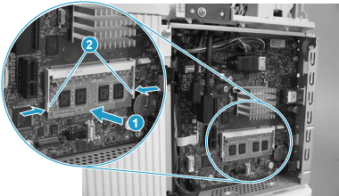
Locate the DIMM component on the formatter, release two locking arms (callout 1), and then let the bottom edge of the DIMM rotate away from the holder (callout 2).Figure : Release the DIMM (M527)

-
Pull the DIMM down and away from the holder to remove it.Figure : Remove the DIMM (M527)

-
Step 4: Unpack the replacement DIMM
Unpack the replacement assembly from the packaging.
CAUTION:
http://www8.hp.com/us/en/hp-information/environment/product-recycling.html
NOTE:HP recommends responsible disposal of the defective assembly.
Figure : Recycle and unpack illustration

Step 5: Install the dual in-line memory module (DIMM)
CAUTION:
NOTE:The M506 printers use a Slim dual in-line memory module (DIMM).
-
M506 only: Push the DIMM straight on the connector to install it.Figure : Install the DIMM (M506)

-
M527 only: Do the following
-
Insert the top edge of the DIMM in the holder.
NOTE:
The DIMM is keyed and can only be inserted in the holder one way.Figure : Insert the DIMM (M527)
-
Rotate the bottom edge of the DIMM toward the holder (callout 1), and then make sure that the two locking arms snap into place (callout 2).Figure : Install the DIMM (M527)
-
Step 6: Install the hard-disk drive (HDD)
NOTE:HDD models only. For all other models, skip this step and go to Step 7: Install the formatter cover.
CAUTION:
-
Before proceeding, take note of the location of the slot (callout 1) in the sheet-metal where the HDD cradle mounting tab (callout 2) must be installed.
CAUTION:
This portion of the sheet-metal is a knock-out plate (callout 1). Do not push on it with sufficient force to detach it when installing the HDD.Figure : Locate the slot in the sheet-metal
-
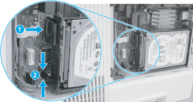
Insert the HDD cradle mounting tab in the slot in the sheet-metal (callout 1), and then rotate the connector end (callout 2) of the HDD toward the formatter.Figure : Install the HDD

-
Make sure that the locking connector (callout 1) latches and that the standoff (callout 2) engages with the slot in the formatter (it might be necessary to pinch the retainer to engage it with the slot).Figure : Install the HDD
Step 7: Install the formatter cover
-
Slide it toward the front of the printer to install it.Figure : Install the formatter cover

https://support.hp.com/
Comments
Post a Comment